Design
The Sea Hog's design was given its name as it represents an effective vehicle that operates underwater.
The figure above shows the side panels we implemented for support and stability to the boat's mainframe. The panels provide stability as the centre of gravity is below the centre of the vessel, thus making the bottom heavy. In addition, the side panels also act as a bumper in the scenario that Sea Hog knocks into a wall.
 |
| Acrylic side panels |
The figure above shows the side panels we implemented for support and stability to the boat's mainframe. The panels provide stability as the centre of gravity is below the centre of the vessel, thus making the bottom heavy. In addition, the side panels also act as a bumper in the scenario that Sea Hog knocks into a wall.


LED position in Sea Hog
The design of the main body was purposed at giving our camera a full frontal view underwater and yet be streamlined for least resistance experienced, hence the usage of the PVC body.
The two circles at the top of the main view port. As shown in the above figure on the right, we used LEDs for proper lighting underwater. The LEDs are energy efficient and require only 1.9V for operation.

Position of motors
For the propulsion of the rover we used four 10 centimetre propellers and two 5.5 centimetre propellers.


Motors' Propellers
The 4 upward facing propellers, in yellow, are used to provide upward or downward thrust to float and submerge the boat respectively. The 2 forward facing propellers, in blue, are used for thrust and provide forward motion.
Of course, we have designed the Sea Hog to be completely watertight. In our prototype testing, we found that the waterproofing solution we used (including copious amounts of epoxy, glue and tape) did not allow even a single drop of water to enter the main electrical compartment throughout the testing program. However, we went to great pains to ensure that there was a safe space for water to flow should leaks develop in the body of the Sea Hog.
Electronics
There is also a composite video output on this camera (the lone unsoldered pin, marked CVBS), however in our prototype we did not use this composite video output.
 |
| Camera Arduino |
The figure below shows the Arduino board used.
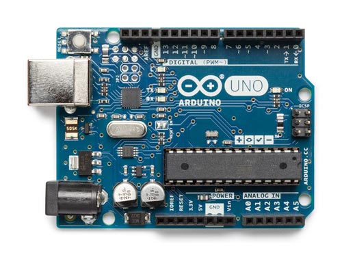
Arduino board
Arduino's dimensions: 100.9mm by 53.4mm
The joystick we used is shown in the figure below.
 |
| Joystick |
The LED we are using are high brightness LED with a potential barrier of 1.9V. The LED are as shown in the figure below.
 |
| High Brightness LED |

H-bridge motor controller chip
The figure below shows the arduino micro used for Sea Hog. Its dimensions are 48 mm X 18 mm.
 |
| Arduino micro |

Motor used
 |
| Power supply board |
 |
| Joystick controller circuit |
 |
| Whole circuit diagram [ Grey colour wires represent to left-right motors Red colour wires represent to up-down motors Black colour wires represent to Gnd ] |
The arduino codes used are provided in the link below:
http://pastebin.com/njJLP0ST
3D sketch of Sea Hog:
http://pastebin.com/njJLP0ST
Mechanics
Due to high strength to weight ratio aluminium has to offer, aluminium flat and L bars were used to link up the structure of Sea Hog.
Due to high strength to weight ratio aluminium has to offer, aluminium flat and L bars were used to link up the structure of Sea Hog.
 |
| Aluminium L bar |
 |
| Aluminium flat bar |
To ensure the main cylinder of the rover was waterproof with the lower possible chance of leaking and collapsing under the pressure the rover has a cylindrical body to distribute the pressure evenly around the cylinder thus lowering the chance for leakages.

Assembling of Sea Hog:
Written by Pei Yong, Keith and Joel
Technical guidance by Lucas and Gabriel
References
RS (2017) Como Drills DC Motor, 7.98 W, 6 → 15 V dc, 78.4 gcm, 9869 rpm, 2.305mm Shaft Diameter Available at: http://sg.rs-online.com/web/p/dc-motors/2389737/ (Assessed 13 February 2017)


No comments:
Post a Comment