Wednesday, February 15, 2017

The Sea Hog - An unmanned vehicle for underwater exploration

The Sea Hog

After many weeks of tedious work, our group, Group 2, has finally completed our project which is to create an underwater rover that can take photos and videos underwater.


Introducing Sea Hog

Sea Hog


Promotion video of Sea Hog

Video also available here: https://www.youtube.com/watch?v=dIvg82rqoPQ


Project Statement


There are many water bodies that need to be inspected but are too hazardous for divers to swim in. Our group presents to you the Sea Hog to tackle this challenge. Sea Hog is required to take pictures of the conditions of water bodies and relay the information to the relevant authorities or organisations. In addition, Sea Hog has to be able to dive to a depth of 1.5 meters.

Technical Specifications


Total Weight
3.4kg
Total Volume
24000 cubicmeters
Maximum Size
400 mm X 300 mm X 200 mm
Materials
Acrylic Plate
3D Printer ABS
PVC
Aluminium L-Bars
Aluminium Flat Bar
Electrical Components
Arduino Micro Board
H-bridge L298
DC motor 6.0-15.0V
Arduino Camera
Arduino Joystick
Arduino Board
High Brightness LED
Controls
Arduino Joystick
Function
 Take photos underwater
Operating Voltage
15 V
Camera Output
USB
Maximum Depth
 1.5 meters


For more information, including a technical deep dive into the design specifics of the Sea Hog, please click here.


How well does it work?

Images captured by arduino camera underwater:

Underwater image of swimming pool
Capturing an underwater image of our swimmer
Underwater image of our lecturer

Note that in this case, we used a computer to capture static images from the Sea Hog's onboard camera, via a FTDI adapter and USB connection. The onboard camera also has a composite video output function which you can connect to a TV, however we did not use that feature in our prototype.

To control the movement of the Sea Hog, we used a joystick that switches between two modes. The default mode controls the movement of the Sea Hog in the horizontal plane, allowing it to move forward, as well as turn left and turn right. The other mode, activated by pressing down on the joystick, allows the Sea Hog to surface or submerge underwater.
Who should get this?

There is a very wide market for underwater exploratory vehicles such as the Sea Hog. Since all you need is a computer or TV to see the output from the Sea Hog's camera, and it's all controlled by a single joystick, the sea hog can be used by anyone, from hobbyists and leisure uses, to even governmental research in areas of science and defense. It truly is a product for everyone.


A word of thanks from the team


These past few months have indeed been a long and arduous journey. Throughout the project, we encountered various setbacks, sleepless nights, and other troubles, but it didn't put us down. In fact, as a learned man once said, "what doesn't kill you makes you stronger." Thus, we had learned more than what we could just sitting in a lecture hall and taking examinations, and our chemistry as a team has also improved much from the first day when we came together to begin this project.
So, from the bottom of our hearts, we thank you for viewing our blog and supporting us all this while. We hoped you learnt something useful from us, as we have learnt over the course of this project.

With our greatest thanks,
  • Lucas, Diploma in Electrical and Electronic Engineering, who was responsible for overall electronics design
  • Gabriel, Diploma in Mechanical Engineering, who was responsible for overall mechanical design
  • Pei Yong, Diploma in Electrical and Electronic Engineering, our coding master
  • Joel, from the Diploma in Electrical and Electronic Engineering, who led the effort to chronicle our progress on the project in this blog, and producing the video
  • Keith, from the Diploma in Aerospace Electronics, who performed the important task of performing mechanical calculations

And of course, we couldn't have completed this project without
  • Our lecturers at the Singapore Polytechnic Engineering Academy, whom provided valuable assistance and support in the course of this past few months.


The Sea Hog - Design Specifics

This information is provided as a continuation of our earlier technical review posts, to help as a deep dive into the final decisions made in the design and construction of the Sea Hog.

Design


The Sea Hog's design was given its name as it represents an effective vehicle that operates underwater.

Acrylic side panels

The figure above shows the side panels we implemented for support and stability to the boat's mainframe. T
he panels provide stability as the centre of gravity is below the centre of the vessel, thus making the bottom heavy. In addition, the side panels also act as a bumper in the scenario that Sea Hog knocks into a wall.


LED position in Sea Hog

The design of the main body was purposed at giving our camera a full frontal view underwater and yet be streamlined for least resistance experienced, hence the usage of the PVC body.

The two circles at the top of the main view port. As shown in the above figure on the right, we used LEDs for proper lighting underwater. The LEDs are energy efficient and require only 1.9V for operation.

Position of motors

For the propulsion of the rover we used four 10 centimetre propellers and two 5.5 centimetre propellers.

Motors' Propellers

The 4 upward facing propellers, in yellow, are used to provide upward or downward thrust to float and submerge the boat respectively. The 2 forward facing propellers, in blue, are used for thrust and provide forward motion.

Of course, we have designed the Sea Hog to be completely watertight. In our prototype testing, we found that the waterproofing solution we used (including copious amounts of epoxy, glue and tape) did not allow even a single drop of water to enter the main electrical compartment throughout the testing program. However, we went to great pains to ensure that there was a safe space for water to flow should leaks develop in the body of the Sea Hog.

Electronics


The Arduino camera we are using is displayed below as figure 1. Its dimensions are 26mm X 18mm X 7mm. This is the main camera being used to take photos underwater.

There is also a composite video output on this camera (the lone unsoldered pin, marked CVBS), however in our prototype we did not use this composite video output.


Camera Arduino

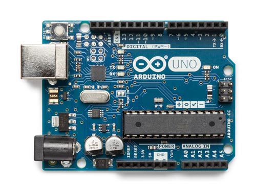
The figure below shows the Arduino board used.

Image result for arduino
Arduino board 

Arduino's dimensions: 100.9mm by 53.4mm

The joystick we used is shown in the figure below.
Joystick
The joystick's dimensions: 38.1 mm X 38.1 mm

The LED we are using are high brightness LED with a potential barrier of 1.9V. The LED are as shown in the figure below.


High Brightness LED
The figure below shows the L298 H bridge motor controller chip that we used.

H-bridge motor controller chip

L298's dimensions: 43.3 mm X 43.3 mm

The figure below shows the arduino micro used for Sea Hog. Its dimensions are 48 mm X 18 mm.
Arduino micro
The figure below shows the motor that our group is using. Its dimensions: 53.5 mm X 32mm X 32mm.

Motor used

The electrical schematics and connections are displayed in the figures below:

Power supply board

Joystick controller circuit

Whole circuit diagram
[ Grey colour wires represent to left-right motors
Red colour wires represent to up-down motors
Black colour wires represent to Gnd ]

The arduino codes used are provided in the link below:

http://pastebin.com/njJLP0ST


Mechanics

Due to high strength to weight ratio aluminium has to offer, aluminium flat and L bars were used to link up the structure of Sea Hog.


Aluminium L bar

Aluminium flat bar

To ensure the main cylinder of the rover was waterproof with the lower possible chance of leaking and collapsing under the pressure the rover has a cylindrical body to distribute the pressure evenly around the cylinder thus lowering the chance for leakages.
   
3D sketch of Sea Hog:


Assembling of Sea Hog:


Written by Pei Yong, Keith and Joel
Technical guidance by Lucas and Gabriel


References


RS (2017) Como Drills DC Motor, 7.98 W, 6 → 15 V dc, 78.4 gcm, 9869 rpm, 2.305mm Shaft Diameter Available at: http://sg.rs-online.com/web/p/dc-motors/2389737/ (Assessed 13 February 2017)


Tuesday, January 17, 2017

Project Update - Making good progress!

It's been a while since we posted our last update, and so far we have made progress in both mechanical and electronics aspects of the design.

Electronics Design

We have pretty much completed the design and fabrication of our electronics components. Here are some pictures:
Figure 1
Figure 2

Programming


Figure 3

Figure 4
Figure 5


Basically, joystick will controls two motors in motor shield and four motors in L298N H-bridge motor controller respectively. The four motors purposely use for the rover sinking and floating whereas the two motors use by the rover to move forward and backwards underwater. The two motors also use for the rover to turn left and turn right. Figure 3 shows how our electronics things connected while we are coding the program. Figure 4 and 5 show our program on how we control the motors by joystick.The full coding for the joystick and the motors will be in the link below. 
http://pastebin.com/2VKUcrTd


Figure 6

Getting visuals from the camera is simple. All we have to do is activate a special serial pass-through mode on the Arduino, so that serial data from the camera is converted to a format the computer can read over USB. Then, it's just a matter of using a special program known as Comtool to control the camera. Here is the link to give the instruction to code a camera program. https://learn.adafruit.com/ttl-serial-camera/using-comm-tool


Mechanical Fabrication

On the other hand, for the mechanical sector, we have made the body and mounted the L bars for the motors. So the mainframe of the rover is more or less done. However, for the head the design had to be redone as the idea of mounting a flat frontal surface was not ideal for waterproofing.


The above pictures show the mainframe of the rover without the head.


Above is the initial design for our head which was scrapped due to its inability to be properly waterproofed.

 For our new head the designed we decided to change it so that the design allow the cap to press fit into the cylinder proving a better water tight seal and but moving the LED mount into the cap we also limit the possibility of leakage thus improving the waterproofness of the body.

Forces

Estimated Forward Thrust = 6.7004 N

Estimated Forward Thrust with safety margin of 1.5 = 10.0051 N

Estimated Upward Thrust = 13.4008 N

The forces are estimated from the data from the experiment conducted in week 4 and 5.

Reflection

From our concept report and other earlier publications, we received some feedback. Here is the feedback, and responses from our team:

1) Can VC0706 Camera Arduino only take an image? Will your camera be providing a feed to a screen or will you be taking pictures?

For this prototype, we will only be focusing on taking pictures at 1.5 meters deep, at locations deemed hazardous for divers. Such environment includes the low oxygen levels, 
water that is polluted or water bodies that have predators that could kill the diver. 

Our camera will be attached to a PC where it shows a live feed of the camera. The desired images will be taken by the controls of the computer, just how you would take photos normally with a digital camera.

2)  How many led you guys using? Why you guys using the normal LED when you guys can use circular LED that gives much more better vision and resolution for the camera?

We are using two 1.9 Voltage High Brightness LEDs. We did consider using circular LED and in fact wanted to use it. However, the circular LED is quite heavy. Given that our robot is already around 3.2kg, by including the circular LED, it will add additional weight will result in more thrust needed to float the boat. In addition, the two LED were tested out and they are bright enough to light up the surroundings, using the circular LED may be an overkill.

3) Where are you guys want to position your motor? Please be more specific.   

We are placing our motor at the horizontal edges of the robot, 3 on the left and 3 on the right. This is to get the most moment out of the thrust of the motors when needing to rotate the robot.

4)  Acrylic is brittle and not suitable for Crash Barrier

The speed of the motor is not fast enough to accelerate the rover to a force large enough to break the acrylic.

5)  Use a memory card shield to back up the pictures you will be taking.

The pictures are sent directly to a PC, which offers the ability to directly save the images to the hard disk.

6) Pictures being not of a decent quality, formatting and size. Unorganised and not detailed images.

Blogger does not have much flexibility in editing our pictures and images, so we had to use. We will make our images more organised and tidy in the future. 


Saturday, December 17, 2016

Project Update - Concept Report

Hello again, it's been a while without any posts, but that's because we've been hard at work.

After considering feedback we received after releasing our Ideation Report, we decided to make some improvements to our design.

Recap

Project Statement

Often images  of structures, wildlife and seabed are required for monitoring and exploration. Divers have limited amount of oxygen in their tanks to get these pictures as well as it is often not safe to dive due to current and pollution. 

Image have to be correctly oriented to be used and a remotely operated vehicle has to be positioned using a control system to attain this orientation.

Can we design and build a remotely operated vehicle that can take pictures at 1.5 meters depth?

In brief


The vehicle will be controlled by a remote control joystick, as well as an external display, that displays visual data sent from the rover's camera.

Detailed concept

This is an ROV that aims to facilitate underwater exploration at approximately 1.5 metres below the water surface.

It will be controlled remotely from a surface point, which the rover is tethered to by its power and data transmission cable. The controller will use a joystick to control the movement of the rover in all three axes, and will use a physical terminal to observe images sent from the rover.


Function analysis

Figure 1: Overall function analysis

Detailed Function Analysis

Figure 2: Detailed Function Analysis

Electronics parts


Figure 3: Camera Arduino

1) VC0706 Camera Arduino
    -take images in JPEG format
    -relay images to a PC or separate monitor
    

Figure 4: Motor Shield

2) Motor Shield
    -easily to control motor direction and speed, for motors providing forward and backwards movement beneath the water.
    -able to power a motor with a separate power supply of up to 12V

Figure 5: Joystick

3) Joystick
    - control motion along the X-axis and Y-axis
    -control the direction of the vehicle


Figure 6: LED

4) LED
    -provide vision so that arduino camera can take picture clearly


Figure 7: H-bridge motor controller chip

5) L298 H-bridge motor controller chip
  The L298 motor controller IC is a fully-featured IC chip that can allow us to control both the speed and direction of a motor. One L298 is already integrated within the Arduino motor shield, however we need a second one to control another group of motors that will be used to surface and submerge the rover.

Flowchart


Figure 8: Flowchart

Wiring diagram

Figure 9: Arduino connection


Figure 10: H-bridge connection


Materials


The primary material for the robot structure will be aluminium. There will be a PVC canister to store the electronics. Figures 11 and 12 list down the materials that will be needed to make this robot.


Figure 11: Material list
Figure 12: Detailed material list


Predicted total weight of robot = 3.2864 x 9.81 = 32.2396 N 

Safety Factor (SF) is set at 1.5,

SF = Buoyancy Force (BF) ÷ Weight

BF = 1.5 x 32.2396 = 48.3594 N

Total Volume = BF ÷ (Gravitational force x density of water)

Total Volume = 48.3594 ÷ (9.81 x 1000) = 0.0049296 cubic-meter

3D Model

Figure 13: 3D model of robot


The rover is designed to be lightweight, durable, and be easily expandable if the need arises. All electronics components will be stored within the cylindrical container in the middle of the rover, while the motors will be mounted to the sides. To prevent any obstacles from interfering with smooth operation of the motors, there is an acrylic panel acting as a sort of crash barrier.


That's all for now, please stay tuned for updates on our prototyping stages!


References

Ezy Strut (2016) Pipe Diameter Charts Available at: http://www.ezystrut.com.au/design/pipe-diameters/ (Assessed 16th December 2016)

CEP (2016) Weight Calculator Available at: http://www.engineeringcivil.com/weight-calculator.html (Assessed 17th December 2016)

SI Metric (2016) specific gravity of metals Available at: https://www.simetric.co.uk/si_metals.htm (Assessed 17th December 2016)


Reference (2016) How do I calculate the weight of aluminium? Available at: https://www.reference.com/science/calculate-weight-aluminum-4340089a015bd6ec (Assessed 17th December 2016)


Lucas

Pei Yong

Joel

Gabriel

Keith